
Arduino Engraving machine, 3d printer expansion board
V2
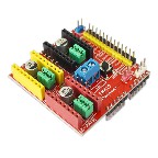
This board is widely used for driver expansion board of
engraving machine,3D printer. There are total 4 ways slots
for stepper motor driver modules, and it can drive 4 ways
stepper motors. Each way stepper motor has two I/O ports
and it means 6 I/O ports can manage 3 stepper motors. It
is very convenient to operate.
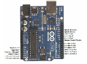
Introduction of Arduino UNO and module I/O port :
These are pins needed for controlling the stepper motors.
Other pins are used in engraving machine or 3D printer,
here no explanation.
Arduino UNO——————-Expansion board
8—————————EN( Enable, low level effective)
7————————– Z.DIR( Direction control of Z axis)
6—————————Y.DIR(Direction control of Y axis)
5—————————X.DIR(Direction control of X axis)
4————————- Z.STEP( Step control of Z axis)
3————————- Y.STEP(Step control of Y axis)
2————————- X. STEP(Step control of X axis)
Program Code Sample:
This is a simple example of stepper motor controller program:
#define EN 8 // Enable, low level effective
#define X_DIR 5 // X axis Direction control
#define Y_DIR 6 //Y axis Direction control
#define Z_DIR 7 //Z axis Direction control
#define X_STP 2 //X axis step control
#define Y_STP 3 //Y axis step control
#define Z_STP 4 //Z axis step control
/*
//FUNC, step Function, Control direction and steps of the
stepper motor
// Parameters, dir, direction control, dirPin is corresponding to
DIR pins, stepperPin is conrresponding to STEP pins, steps
are stepper motor steps
//No return value
*/
void step(boolean dir, byte dirPin, byte stepperPin, int steps)
{digitalWrite(dirPin, dir);
delay(50);
for (int i = 0; i < steps; i++) {
digitalWrite(stepperPin, HIGH);
delayMicroseconds(800);
digitalWrite(stepperPin, LOW);
delayMicroseconds(800);
}
}
void setup(){ Set I/O ports used for stepper motor to OUTPUT
pinMode(X_DIR, OUTPUT); pinMode(X_STP, OUTPUT);
pinMode(Y_DIR, OUTPUT); pinMode(Y_STP, OUTPUT);
pinMode(Z_DIR, OUTPUT); pinMode(Z_STP, OUTPUT);
pinMode(EN, OUTPUT);
digitalWrite(EN, LOW);
}
void loop(){
step(false, X_DIR, X_STP, 200); //X axis stepper motor
rotates 1 circle counter-clockwisly, needing 200 steps
step(false, Y_DIR, Y_STP, 200); // Y axis stepper motor
rotates 1 circle counter-clockwisly, needing 200 steps
step(false, Z_DIR, Z_STP, 200); // Z axis stepper motor
rotates 1 circle counter-clockwisly, needing 200 pulses,
delay(1000);
step(true, X_DIR, X_STP, 200); //X axis rotates 1 circle
clockwisly, needing 200 steps
step(true, Y_DIR, Y_STP, 200); // Y axis stepper motor rotates
1 circle clockwisly, needing 200 steps
step(true, Z_DIR, Z_STP, 200); // Z axis stepper motor rotates
1 circle clockwisly, needing 200 steps, delay(1000);}
Experiment phenomena, stepper motor rotates 1 circle
counter- clockwise, delay one second, and then rotate 1 circle
clockwise, like this, etc.
Attention, please! Don’t make a mistake of the driver
module A4988 direction. The connection of stepper
motor is 2A (RED), 2B (GREEN) a phase, 1A (BLUE), 1B
(YELLOW) a phase. If you want to change the direction,
just change 2A to 2B or 1A to 1B.